A Path equipment allows a product to move along a path.
The Path equipment is only available from version 5 of Sym3
From the Toolbox, simply drag and drop a Path into the simulation.
From the Project Explorer >System > Equipment > Path.
Or directly in the simulation.
Coordinates: List of coordinates. Each coordinate contains 4 values (X, Y, Z and Bulge). Adding a Bulge is for defining a part of the path where opposing objects can be configured to cross. The bulge formula is:
Note that as at V5.2 only the coordinates for the first section is displayed, in newer versions this will be expanded to allow all sections to be edited. At this point all creation and editing should be performed through macros.
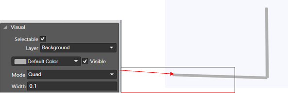
Mode: New property in visual category of path as Mode. The path mode can be changed to.
• Quad (default mode)
In quad mode able to change the width of the path
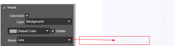
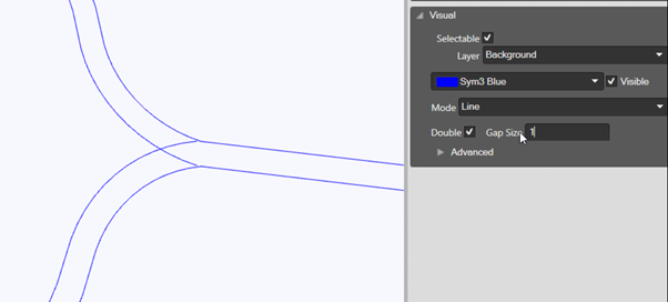
• Line mode
The line width cannot be changed
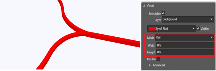
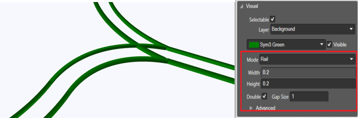
• Rail mode
New render mode for the path Rail. The 2D path will change to 3D shape which extrude along it. When the mode changed to Rail, a new property will add in visual category as Height of the shape.
In all mode, we are able to change path color and visibility.
Line Width: Default 0.1. Width of the line in the units chosen when the project was created (metres or feet).
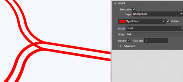
Double: New property in visual category of path as Double. When tick the double checkbox the single path will change to double path with a gap between it. The gap size can be adjustable.
This property is available for Quad, Line and Rail mode.
Gap size value: Min: 0 Max: 10000 Default: 0.1
• Quad (Double mode)
• Line (Double mode)
• Rail (Double mode)